Create ROOM (Real-Time Object-Oriented Modeling) diagrams
Create ROOM (Real-Time Object-Oriented Modeling) diagrams
The ROOM modeling language is used to model real-time systems. ROOM is a blend of advanced object-oriented concepts and traditional real-time software techniques. You can use ROOM to build a graphical model of a system's components and their relationships (the structure), and of the system's response to events (its behavior).
For information about the ROOM methodology, refer to "Real-Time Object-Oriented Modeling" by Bran Selic, Garth Gullekson, and Paul T. Ward (John Wiley & Sons, Inc., 1994).
What do you want to do
Create a ROOM structure diagram
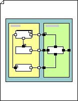
A ROOM structure diagram illustrates the major components of a system.
The primary components of a ROOM structure diagram are actors, which are active objects with a clearly defined purpose. Actors are based on actor class definitions, and inherit the properties of those definitions. A structure diagram represents actors and their relationships.
Actors communicate with other actors through ports, which are an actor's interface components. Bindings represent communication paths between actors.

-
On the File menu, point to New, point to Software and Database, and then click ROOM.
-
Drag the Actor class shape from ROOM onto the drawing page.
-
Name the shape by selecting it, and then typing.
-
Drag an Actor reference shape or a Modified actor ref. shape onto the drawing page, and place it inside the Actor class shape.
Note: To change the Modified actor ref. object type at any time, right-click the shape, and then click Select Actor Reference Type.
-
Drag a port shape onto the drawing page, and then connect it to an actor shape.
Note: To change the port type later, right-click the shape, and then click Select Reference Port or Select Relay Port.
-
Drag a Binding shape onto the drawing page, and then connect it to port shapes to represent a communication path between ports.
-
If your ROOM diagram includes ROOM layers, add additional layer or export connector shapes to connect the different layers.
Create a ROOM behavior diagram
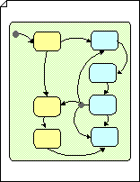
A behavior diagram illustrates the implementation, or behavior, of an actor. ROOM behavior diagrams are also called ROOMcharts.
The primary components of ROOMcharts are states, during which objects are receptive to new events, and transitions, during which objects change from one state to another. State context, comprised of a nested series of states, represents the current state of a system.
Each state represents a period of time during which the actor exhibits a particular behavior. Transition points represent either the start or ending point of a transition between state contexts.
In ROOM modeling language, you can simplify large systems by assigning to layers any implementation-level services shared by a large number of actors. Actors that can extend vertically as well as horizontally model the layers. Just as a binding represents a communication between ports, layer connectors and export connectors represent communication between layers in your structure.

-
On the File menu, point to New, point to Software and Database, and then click ROOM.
-
Drag a State context shape from ROOM onto the drawing page.
-
Name the shape by selecting it, and then typing.
-
Drag a State shape onto the drawing page and place it inside a State context shape.
-
Drag a Transition points shape onto the drawing page and connect it to a State shape.
Note: To change the transition point type at any time, right-click the shape, and then click Select Transition Point Type.
-
Drag special transition shapes, such as Group transition, Internal self-transition and Transition to history shapes, onto the drawing page, and then connect them to State shapes.
-
Drag a Transition shape onto the drawing page and connect it to State shapes.
Note: If a transition splits into multiple paths, drag a Choicepoint shape onto the drawing page, and then connect the diverging transitions to it as an origin point.